 Please
read these instructions completely before you start the installation.
Familiarizing yourself with all of the components mentioned will make
the installation much easier.
Please
read these instructions completely before you start the installation.
Familiarizing yourself with all of the components mentioned will make
the installation much easier.U.S. Gear Corporation, 1020 W119th, Chicago, IL 60643 -- Phone 888-874-3275
Dual Range Electrical
Installation
ALL MODELS
Please
read these instructions completely before you start the installation.
Familiarizing yourself with all of the components mentioned will make
the installation much easier.
(Graphics appear at bottom of document.)
AUTOMATIC TRANSMISSION
The Dual Range electrical wiring for the automatic
consists of a two-circuit system. The first, the control circuit,
includes the shift control module, and gray signal switches, protected
by an in-line, low amperage fuse. The second, the power circuit,
includes the control module and the shift motor protected by a 15 amp
automatic re-set circuit breaker.
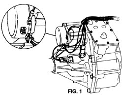
Under Vehicle
With the Dual Range installed and
the vehicle raised, start the harness installation at the right side
cover of the Dual Range as follows:
Plug the green terminal with the brown and white wire into the motor
(Fig. 1). Attach the green ground wires to the existing screw at the
rear of the shift motor.
Plug the signal switch wires on to the appropriate gray switch:
Underdrive: Orange and green wire to front side switch, black and green wire to rear switch.
Overdrive: Orange and green wire to rear switch, black and green wire to front side switch.
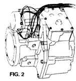
Circle harness up and forward and attach with "J" clip to upper top side cover bolt (Fig. 1 or Fig. 2).
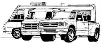
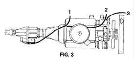
Run the main harness up the back of the transmission and through the
engine compartment in the left rocker cover area. Pickup trucks exit at
point 1, vans and Class "C" motor homes point 2 and Class "A" motor
coaches point 3 (Fig. 3). Lower the vehicle and continue the underhood
procedure.
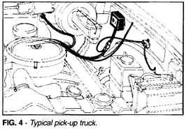
Under Hood
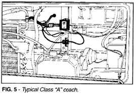
Locate a cool area for the control module and mount
(Fig. 4 and Fig. 5). Pickup trucks have adequate firewall or side panel
room, but vans and Class "C" homes are tight. We suggest wire tying the
control module to an existing object (harness, etc.) located in an
active air area. Ground the green wires to an appropriate body panel
and mount the circuit breaker within the length of red harness wire.
Attach the red harness wire to the "Aux" side of the circuit breaker
and within the length of red harness wire. Attach the red harness wire
to the "Aux" side of the circuit breaker and attach loose red wire
provided to the "Bat" side of the circuit breaker and attach to an
appropriate 12-volt source (direct to "+" post of battery or junction
block).
Run the harness for the shift module through the firewall using existing openings or provide a new hole for same.
Caution: Be very sure that all wires are properly protected where they pass through the firewall.
Passenger area
Install the shift module on the gear shift lever in the
most comfortable position for the thumb to reach and for viewing the
high and low lights. Wire tie the wiring harness to the shift lever and
pass under the dash and plug into the main harness. Run the in-line
fuse holder wire to a 12-volt source that is off when the ignition key
is in the "oft" position.
Caution: Do not shift the Dual Range while in park or neutral or when the vehicle's cruise control is engaged.
MANUAL TRANSMISSION
The Dual Range electrical wiring for the manual
transmission uses a simple power circuit consists of a vertical
push-pole shift switch, a six wire version of the control module, and
the shift motor, all again protected by a 15 amp automatic re-set
circuit breaker. No indicator lights are used; the gear selection is
indicated by the up or down position of the shift switch.
Under Vehicle
The manual transmission harness has only two wires to be
connected to the Dual Range. Plug the green terminal with the brown and
white wire into the motor as shown in Fig. 1 of the automatic
transmission.
Underdrive: White wire to front terminal.
Overdrive: Brown wire to front terminal.
Use the "J" clip in the upper front screw of the side cover. Feed the
two-wire harness to the transmission and up the shift lever through the
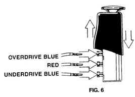
rubber boot, position the shift switch as preferred. Plug the wires in
the switch as pictured (Fig. 6). Blue wire to the
top for overdrive…Blue wire to the bottom for underdrive. Wire tie the harness to the shift lever.
Run the four wire harness under the vehicle following the floor pan
to the firewall. Plug the six-wire male terminal into the female
terminal of the control module in a cool active air area (firewall,
fender panel, etc.). Run red wire from control module to "Aux" post of
the circuit breaker; green wire remaining, to a good ground. Attach red
wire provided to the "Bat" side of the circuit breaker and attach to an
appropriate 12-volt source (direct to "+" battery or junction block).
|
|
|
|
|
 |
|
|
|
|
|
|
|
Parts List (Automatic) |
|||
| Item | Part Number | Description | Qty. |
| 1 | 59-80007 | Shift module | 1 |
| 2 | 93-80042 | Main wiring harness | 1 |
| 3 | 59-80011 | Control module | 1 |
| 4 | 80-80024 | Circuit breaker kit | 1 |
| 5 | * | Power lead | 1 |
| 6 | 59-80004 | Gray limit switch | 2 |
| 7 | 80-80031 | Gray limit switch, gasket | 2 |
| 8 | * | Wire ties | 6 |
| * Included with wiring harness (Numbers refer to rendering for automatic) |
|||
|
Parts List (Manual) |
|||
| Item | Part Number | Description | Qty. |
| 1 | 93-80029 | Push-pull shift switch | 1 |
| 2 | 90-80144 | Mounting bracket | 2 |
| 3 | 93-80043 | Main wiring harness | 1 |
| 4 | 59-80012 | Control module | 1 |
| 5 | 80-80024 | Circuit breaker kit | 1 |
| 6 | * | Power lead | 1 |
| 7 | * | Wire ties | 6 |
| * Included with wiring harness (Numbers refer to rendering for manual) |
|||
Return to Dual Range Product Page
Return to Installation Page
Send your questions and comments to: info@usgear.com
Copyright © 2006 U.S. Gear
Last modified:
06/06/08

